Pagina's op IkLeerBIM

Posts tonen met het label Dynamo. Alle posts tonen

dinsdag 8 juli 2025

Tool om een Revit Project af te stemmen op de Nederlandse BIM standaarden -UPDATE REVIT2026-

Bij deze de 3e grote update van deze tool om een lopend Revit project in 1x grootschalig af te stemmen op eisen uit de BIM Basis ILS en Revit Standards. Al die jaren zijn wij er als RoosRos mee blijven werken en hebben het zo steeds weer iets beter kunnen maken. 


De tool werd eerst gedeeld op 30 september 2017. Een 1e grote wijziging werd gedeeld op 12 februari 2018. Met enkele verbeteringen en meer toelichting. De 2e grote wijziging werd gedeeld op 13 september 2022. Die was onder andere afgestemd op de nieuwe IFC parameters van Revit. En nu dus de 3e grote wijziging voor Revit 2026. Deze versie heeft meerdere verbeteringen. En het is afgestemd op Dynamo 3+ met o.a. CPython Nodes.

kijk een kort filmpje wat de tool doet 


In hele grote lijnen zijn de verbeteringen als volgt:

  1. IfcName, LoadBearing en IsExternal staan nu standaard aan (mits al aanwezig in je Revit project). En je kan nu makkelijk een parameter 'overslaan' en niet laten aanpassen in Revit door de betreffende parameter in rij 5 te verwijderen. Via de drop-down kan je dit ook weer snel terugzetten als de hele Excel kolom gecontroleerd en akkoord is.  
  2. Er zijn meerdere nieuwe NLRS categorieën toegevoegd op basis van de nieuwe Revit versie.
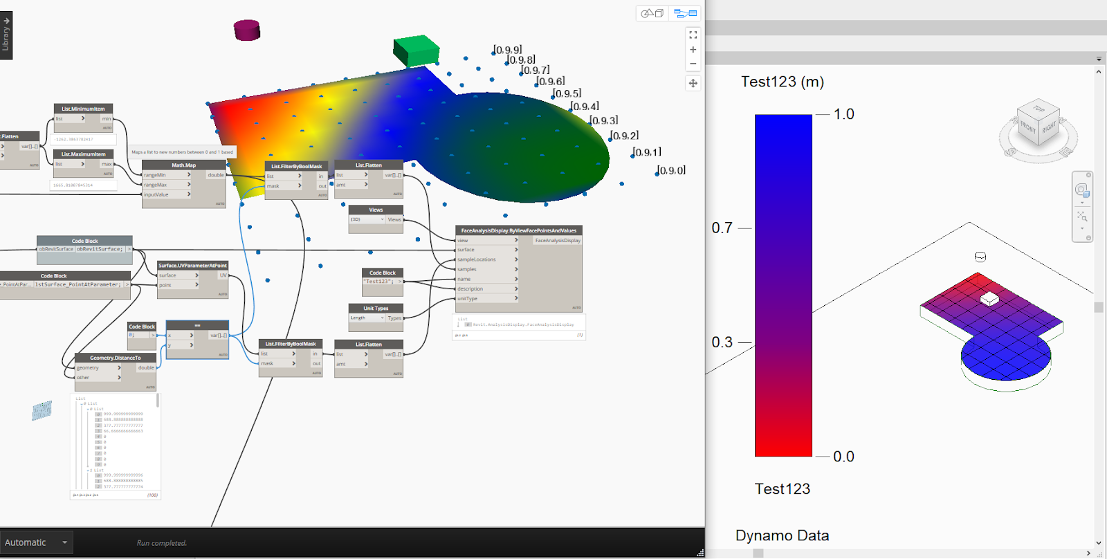
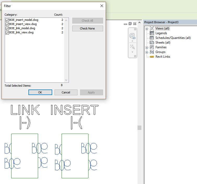
  3. Niet heel spannend maar er is nu een uitleg en 'afbeelding' aan de scripts toegevoegd voor de Dynamo Player.


In Dynamo en in de workflow zijn enkele grotere aanpassingen nodig geweest:

  1. De Excel Nodes zijn inmiddels niet meer aanwezig in Dynamo 3+. Deze zijn vervangen door XML Nodes. In basis prima. Maar het bleek noodzakelijk om in aparte Excel bestanden te werken. Deze worden automatisch geladen in het Excel invulblad wanneer die geopend wordt. Dit automatisch laden van gegevens in Excel moet dus aan staan of aangezet worden. 
    .. en het antwoord is ja
  2. De XML Nodes openen het bestand niet na wegschrijven. Daar is met Python een toevoeging voor gemaakt. Het zal praktisch niet voorkomen. Maar de XML read node laat de data in Excel niet  op de achtergrond inlezen. Dus het is belangrijk dat de Excel eerst wordt opgeslagen en gesloten. Zodat de laatste gegevens daadwerkelijk door de XML node worden geladen. Er gaat niks kapot. Maar het script doet dan gewoon niks. Want voor de XML node is de xlsx leeg. ;-)
  3. In de situatie dat het nodig is om script 02b toe te passen (sla Model Groups over) lijkt het verstandig Revit opnieuw op te starten. Dit komt soms doordat er door Model Groups een te complexe structuur in Revit is ontstaan. Revit kan onderdelen dan niet aanpassen. Doordat het dynamo script wordt afgebroken (je wil geen gesplitste Model Groups)  lijken er toch processen open te blijven staan. Met undo, opnieuw opstarten en het runnen van script 02b kan je toch zo veel mogelijk aanpassingen doorvoeren.
  4. Alle Custom Nodes in Dynamo zijn weer nagelopen en in basis geüpdate naar de laatste wijzigingen van de package. Meerdere Nodes uit ClockWork zijn voor het gemak iets veranderd zodat het script niet teveel veranderd hoeft te worden. ! De meegeleverde Nodes zijn dus echt nodig en moeten in dezelfde directory worden gezet (waarschijnlijk een aparte dir op je netwerk) Alle Python Nodes zijn nu CPython. 


Als je de tool eens wil uitproberen is het stappenplan als volgt:

  1. Als je deze tool nog nooit hebt gebruikt. Kijk dan eerst eens het bovenstaande korte stoere filmpje om gevoel te krijgen bij het einddoel van deze tool.  En lees vervolgens de laatste blog eens door. Er zijn elke keer wel weer verbeteringen geweest die het werken verbeteren. De Excel wordt nu bijvoorbeeld elke keer gekopieerd naar het directory van je project. Het handmatige kopieerwerk van de Excel en in de Excel is daarmee niet meer nodig. 
  2. Sla je project op. En zorg dat je eventueel terug kunt naar je eigen oude situatie. Purge vervolgens alles wat niet echt nodig is. Dat vertraagt de boel alleen maar. Tijdens deze workflow mag er niet in het Revit project gewerkt worden. Een nieuwe of gewijzigde Id blokkeert bewust het aanpassen in Revit.
  3. Download de tool. En unzip alles op een mooie plek. De oude (Dynamo) versies zijn in de zip nog aanwezig. Maar de laatste versie is natuurlijk het meest ver ontwikkeld. 
    inhoud zip ... versie 3.0 is het meest up to date .. rest als archief
  4. Run het 1e script van Revit naar Excel. Excel zal uiteindelijk openen. Mogelijk krijg je de vraag of een extern bestand in Excel geladen mag worden. Dat is inderdaad nodig. Als alles geladen is kan je in het groene tabblad wijzigingen gaan voorbereiden. Bij het openen zit je onder in de tabel. En ziet  wat toelichtingen per kolom. Scrol dus omhoog om de inhoud uit Revit te zien.
    1. Werk per kolom -en niet per rij- onderdruk deze neiging, zo werken helpt hier niet.
    2. Begin altijd bij de Assembly Code in kolom S of T. Bijna alles heeft hier een relatie mee. Let op 31.10 en 32.10 zijn openingen en geen kozijnen.
    3. Loop de IFC parameters na, Je zal zien dat er al veel voorstellen zijn gedaan op basis van de NL-SfB en/of de Revit Category. Met drop-down menu's kan je eventueel een alternatief kiezen voor IFC entiteit en enumeration.
    4. Loop snel IsExternal en LoadBearing na. Ook deze volgen de NL-SfB.
    5. Bij de volgende stap moet je een keuze maken. Family Name, Type Name en IfcName kosten simpelweg wat extra tijd. Ik zou dit óf wel óf niet gaan doen. Als je deze niet doet, maak dan de relevante kolomkoppen in rij 5 leeg. Dat voorkomt dat er straks onbedoeld wijzigingen worden doorgevoerd (deze zijn groen aangegeven) Als je deze onderdelen wel wilt aanpassen. Begin dan bij de Family Name. Vervolgens de Type Name. En speel daarbij eens met de getallen in de naast liggende blauwe kolommen. Hiermee kan je de omschrijving langer (+getal) of  korter (-getal) maken. IfcName is samengesteld uit de omschrijving van Family of Type gecombineerd met de NL-SfB. 
    6. Sla de Excel op. En sluit Excel af.
  5. Run vervolgens het 2e script Excel naar Revit. Afhankelijk van hoeveel wijzigingen er worden doorgevoerd (zie AN3 en AN4) en de complexiteit van project zal het korter of langer duren. 
    1. Als je véél met Model Groups én met Shared Nested Families werkt kán het voorkomen dat Revit een wijziging niet zomaar kan doorvoeren. Je krijgt dan de vraag of je de Model Groups wilt ungroupen. Waarschijnlijk is dan het antwoord NEE. Sluit Revit af en sla je project niet op. Start het Revit Project opnieuw. En run het alternatieve script 02b. Alles wat in een Model Group zit zal dan worden overgeslagen.
    2. Alles wat -om redenen- niet is aangepast, maar ook alles wat wel is aangepast, zal gerapporteerd worden. Loop de resultaten en de probleempjes even kort na om te weten wat er is is gebeurd in Revit. Dat verhoogt ook het gevoel bij zo'n tool als dit. Er gebeurd in werkelijkheid niks wat je niet ook handmatig had gekund.

De nieuwe versie is HIER te downloaden of via Github.


Sla het project veilig op voor je met dit soort grote scripts aan de gang gaat. Wij werken er ook gewoon mee. Maar als het fout gaat is er wel heel veel fout aangepast. Dit is geen commercieel product met bijbehorende garanties. Zorg dat je zelf een back-up hebt. Geniet en gebruik de tool, maar wel op eigen risico.
Als er vragen of opmerkingen zijn hoor ik dat natuurlijk graag. Daar hebben we allemaal wat aan! Meerdere mensen zijn je al voor geweest. Tot nu toe was allemaal goed en snel oplosbaar.


Ook namens RoosRos architecten veel werkplezier met deze tool! 
Een tool voor het werken met de BIM Basis ILS en de Revit Standard. 
Bouwen met BIM doe je samen!

vrijdag 7 oktober 2022

Custom Dynamo Node - RoomSolidIntersectionByParameterValue

Vandaag het vervolg op mijn vorige post. In mijn vorige post vertelde ik over de node RoomsToSolidRepresentation. Het was een lange post. En vandaag gaat het over een toepassing hiervan. Dat kan gelukkig wat korter. Bij deze RoomSolidIntersectionByParameterValue

Nadat we een gesloten en betekenisvol analytisch model hebben gegenereerd van een live project -een eerste stap naar een Topological model zeg maar-, kan je beginnen met een paar analyses. Je kan bijvoorbeeld eigenschappen hangen aan de snijvlakken tussen de ruimtes. Denk concreet aan brandscheidingen en bijv. geluideisen. Dit zijn de vakjes 4.5 en 4.6 uit de BIM Basis ILS. Maar er zijn vast meer toepassingen denkbaar. ;-)

RoomSolidIntersectionByParameterValue = dit dus.

Het hele proces bestaat uit een paar stappen:
  1. Je gebruikt de Node RoomsToSolidRepresentation, en maakt zo lijsten met Solids en Rooms.
  2. Je kiest een Room parameter als sturing voor de analyse. En koppelt vervolgens de Parameter naam, de Solids en de Rooms aan de Node RoomSolidIntersectionByParameterValue
  3. Open de CSV die de Node gemaakt heeft. En vul de eisen in.
  4. Run het script nogmaals. De Node zal dan de ingevulde waardes van de CSV gebruiken en vlakken en bijbehorende waardes rapporteren
  5. Doe er wat leuks mee! Pas Revit aan: plaats DirectShapes, plaats Families, selecteer Revit objecten en pas eigenschappen aan. Of blijf nog in Dynamo en tweak het gegenereerde. Of exporteer de data, bijv. met de Topologic Package. Je kan dan in je eigen software verder. Of gebruik Rhino, Blender of ...

Laten we deze stappen eens stap voor stap nalopen en gebruiken 'het Revit huis' als referentie.

vrijdag 30 september 2022

Custom Dynamo Node - RoomsToSolidRepresentation

In mijn IkLeerBIM Dynamo Package zitten enkele Nodes waar ik het over wil hebben. Waarom heb ik ze gemaakt. Wat doen ze. En hoe werken ze. Vandaag RoomsToSolidRepresentation.


Ik ben bezig geweest om met Dynamo een sterk vereenvoudigde representatie te genereren van een gebouw. Dit moet werken in elk stadium van een lopend project. De basis van deze representatie zijn ruimtes. En daarnaast levels die als building storey zijn aangemerkt. Het resultaat is een groep volumes die compleet aaneengesloten een nieuw ‘gebouw’ volume vormen, zonder gaten. 
Zo veel mogelijk een Topologic model zeg maar.


Toepassingen zijn logischerwijs voor allerhande analyses. Hoeveelheden, Energie, daglicht, logistiek etc. Een schematische weergave is in veel gevallen zinnig omdat in een live project vaak te veel en te gedetailleerde informatie zit. Het klinkt een beetje tegenstrijdig. Maar te veel info maakt een snelle analyse vaak traag en soms zelfs onmogelijk. Ik denk dat we in de toekomst soepel heen en weer moeten kunnen van schematisch naar gedetailleerd en terug. En dit proces moet zich meerdere keren kunnen herhalen, voor zover nodig. 

In principe is het plug and play. Maar mogelijk krijg je een onverwacht resultaat bij een snelle test. Vandaar een (uitgebreide) toelichting. 😉

dinsdag 13 september 2022

Tool om een Revit Project af te stemmen op de Nederlandse BIM standaarden -UPDATE REVIT2023-

5 Jaar! 🥳

5 Jaar geleden publiceerde ik namens RoosRos architecten een tool om een Revit project sneller en efficiënter af te stemmen op enkele BIM standaarden. 
De Revit Standards. En natuurlijk de BIM Basis ILS
In de laatste 5 jaar zijn er meerdere grote en kleine updates doorgevoerd. Als ik Google Drive mag geloven wel 21 versies. Maar nu met Revit 2023 moest er een grotere wijziging worden doorgevoerd, omdat Revit de belangrijkste IFC mapping parameters heeft veranderd, vereenvoudigd en verbeterd. 
Fijn!
kijk een kort filmpje wat de tool doet 


zie het introductiefilmpje van Autodesk  


Wat zijn die IFC veranderingen in Revit 2023 nou in detail? En wat is het nut van het updaten van die BIM standaard tool?

Zoals je in het filmpje kan zien heeft Revit 3 extra Instance en 3 extra Type parameters gekregen. Die parameters zorgen voor de mapping tussen Revit en IFC. Deze nieuwe BuiltIn parameters worden met met een apart menu of dropdown gevuld. En zijn niet als tekst aan te passen in Revit. Zo voorkomen we tiepfouten. Het updaten van oude projecten naar Revit 2023 ging bij ons ... automatisch en vooralsnog prima.

Dat zo'n mapping tussen Revit en IFC een dingetje is, komt omdat de structuur van Revit en IFC niet 1 op 1 is. Niet elke Revit Wall is een IfcWall, en niet elke Generic Model wil je als IfcBuildingElementProxy in een IFC zien, etc. 

Hoe bepaal je dan wat die Revit Wall of Generic Wall wel zou moeten zijn? Daar helpt die BIM Standard tool dus wat mee. In de eerste plaats door een suggestie te geven  op basis van de Revit Categorie. Een Wall is vaak wel degelijk een IfcWall. Maar in combinatie met de NL-SfB code die je opgeeft, zal er eventueel een alternatieve suggestie worden gegeven. Twijfel je nog steeds. Dan kan je door op de hyperlink te klikken (>>), direct naar de IFC website van BuildingSmart. Daar wordt uitgelegd waar elke IFC entiteit of Enummeration Type voor bedoeld is. 

Maar de NL-SfB geeft ook aanleiding voor de Function parameter. Dit is de BuiltIn parameter die binnen Revit aangeeft, of een wand of kozijn, bijvoorbeeld binnen of buiten is. En daarnaast komen de 1e 2 cijfers uit de NL-SfB ook terug in de naam van objecten in Revit. Deze benaming komt vaak terug in een IFC. (Al hoeft dat niet persé)

Het moge duidelijk zijn, dat deze tool er voor zorgt, dat er samenhangende informatie ontstaat. Dit is noodzakelijk als je ook maar iets met data wilt doen (en machine learning niet in je skillset hebt) En een computer is simpelweg beter in structuur, dan goedwillende mensen die alles handmatig doen. Ook helpen ingebouwde suggesties, om spelenderwijs, de mapping steeds nauwkeuriger te maken. 
We zijn als jonge kinderen allemaal begonnen met het uitspreken van een paar woordjes. En wat waren onze ouders trots! Spelenderwijs leren mensen steeds meer woorden, om beter te zeggen wat we bedoelen. Professioneel is dat niet heel anders. Steeds een stapje vooruit.

Testen of gebruiken?

Wil je eens testen wat er bij het updaten naar een Revit 2023 project nou precies gebeurd? Download dan het eenvoudige voorbeeld bestand met een paar objecten erin. Deze hebben de verschillende voorkomende oude mapping instellingen. Je kan dit bestand ook gebruiken om de BIM standard tool eens zorgeloos te ‘gebruiken’. 


Zin om ook de tool een keer te proberen?
Download dan hier of via Github de laatste versie. Je kan de scripts gebruiken uit de map die matched met je eigen Dynamo versie. Voor Revit 2023 is dat op dit moment Dynamo2.13.  Kijk zeker het uitgebreide filmpje waar ik door de BIM standaard tool heenloop. Ondanks dat sommige details door de jaren heen iets verbeterd zijn, geeft het een goed beeld van hoe de tool werkt. 
Hieronder een paar belangrijke punten vooraf:
  • Het gebruik van de tool is helemaal vrij, maar wel op eigen risico. Ik moet dit voor de duidelijkheid wel zeggen. Maar bij RoosRos gebruiken we de tool ook gewoon om projecten op een iets hoger niveau te krijgen.
  • Synchroniseer altijd eerst voor je gebruik maakt van een Dynamo Script.
  • Voorkom dat je in Excel verder werkt met handmatige aanpassingen die de vorige keer gemaakt zijn. Reset het Excel document na een import, door in de Sheet Dynamo_Read, 1 van de 2 onderste rijen over het hele invulveld tot de gele headers heen te kopiëren. Dat reset alle input, opmaak en formules van je invulveld.
  • Het doorlopen van meerdere eigenschappen van alle Types in je Revit project kost simpelweg tijd. Afhankelijk van je ervaring en de grote van het project kan het zomaar een aantal uur kosten. (het minimale Revit 2023 voorbeeld bestandje is natuurlijk wel razendsnel)
    • Kies dus een rustig moment en doorloop alle handelingen voor je verder werkt in Revit. Als Revit wordt aangepast -voordat alle wijzigingen zijn terug geschreven- wordt het import script mogelijk afgebroken. En moet je daaarom veel dingen opnieuw doen. :-(
    • Kom je erachter dat je niet alles wilt doen. Of heb je niet voldoende tijd. Wees gerust, je kan best delen overslaan. Gooi dan de invulvelden leeg van de onderdelen waar je niet bewust naar gekeken hebt. Daarmee voorkom je, dat alle suggesties die Excel automatisch doet, worden overgenomen in Revit. Heel praktisch: verwijder de formules voor het aanpassen van de Family of Type benaming, en concentreer al je aandacht op de Assembly Code. Loop dan snel de IFC mapping na en synchroniseer de resultaten terug. Een volgende keer kan je de benaming wel doen.
  • Werk van boven naar beneden.. En begin bij de Assembly Code. Check daarna snel de IFC mapping. Let daarbij vooral op IfcOpening (=31.10 en 32.10) en IfcSite. IfcOpening alleen gebruiken als er geen zichtbare Geometry aanwezig is – dus nooit bij kozijnen. Maar ook niet per definitie bij een sparingmaker. Beperk de IfcSite mapping zoveel mogelijk tot de Toposurface. En eventueel een 0-punt object. Gebruik IfcSite niet bij vrachtwagens, of inrichting ofzo. En liever ook niet bij een Floor die een lastige Toposurface moet vervangen. (rule of thumb)
Als je dit gedaan hebt loop dan nog sneller de Function en eventueel de Manufacturer na.Gebruik de rest van de tijd om Family en Type benaming na te lopen. Gebruik ‘de blauwe kolommen’ om meer of juist minder karakters uit de oude benaming over te nemen.


Als er vragen of opmerkingen zijn hoor ik dat natuurlijk graag. Daar hebben we allemaal wat aan! Meerdere mensen zijn je al voor geweest. Tot nu toe was allemaal goed en snel oplosbaar.


Ook namens RoosRos architecten veel werkplezier met deze tool! 
Een tool voor het werken met de BIM Basis ILS en de Revit Standard. 
Bouwen met BIM doe je samen!


donderdag 22 oktober 2020

Update IkLeerBIM Dynamo Package

The IkLeerBIM Dynamo package has just been updated.

more methods, more arguments,
ready for Revit 2021,
and what about sandbox and other software.


A few things have improved or changed:
  • Some Python 'build in functions' did not show up as a method. This error is fixed.
  • The Revit API 2021 has deprecated the displayUnitType in Revit 2021. So based on the Revit version the script uses displayUnitType or ForgeTypeId.
  • The LookUp node and MethodLookUp node should also work in Dynamo Sandbox or other software. So the UnwrapElement and the loading of some libraries are made conditional.
  • The MethodLookUp node now also can deal with 'overloads'. Cases were more than 1 argument series for a method is possible in the API.
  • The Example.dyn file in the Extra directory is also updated to the new functionality.

Thanks Laurin Ernst, for the feedback!

Older posts about this Dynamo Package:

dinsdag 5 mei 2020

Update IkLeerBIM Dynamo Package

Just added 2 extra nodes: API.MethodLookUp and API.FilterScriptGenerator.
And in the extra directory is also an example.dyn file for a Quick start.


The whole goal of this Package is to help people who are already familiar with Dynamo. And understand how to make a for loop in Python. So they can find their way with the (Revit) API as comfortable as possible. You can search the internet later. Most Dynamo users will come to this point where they need to build just a little Python script because there is no Node available. Or they need to speed up a Dynamo script just a little.

To do this I needed to add 2 more Nodes:

API.FilterScriptGenerator 

Will help you with your second problem: "How to grab elements from the Revit Database?" You can use the Dynamo Nodes off course. But can you do without? Now you can. And very easy. This Node will generate a complete Python Script. Copy this to clipboard, with a Node from Clockwork or Rhythm. Paste it in a Python Node. And tweak it to your needs.

API.FilterScriptGenerator

But, "The FilterElementCollector is no rocket science." I hear you say. No it isn't.
Still this Node has almost every option that the API gives us. And there are quite a few...
Beside filtering on 1 or multiple Classes or BuiltinCategories, you can Filter on all the Parameters you want. Use Views, Levels, Geometry and DesignOptions. And there is also an option so your Python Node also works for Linked documents.

Some Filter options can be achieved in multiple ways. If that is the case I tried to choose 1 or the other. I also skipped some very specialized Filters, because it is possible to also use e.g. BuiltinCategories. Most of this is documented in the Node.
And for those who know their stuff. This is not the most beautiful, clean and efficient script I ever wrote. But it works. ;-) So perhaps I will clean it up later (if I want to).


API.MethodLookUp 

Helps to find the arguments needed for a method. In al lot of cases this will be enough. And if this is still confusing you can always use google and find more examples or an explanation.
API.MethodLookUp
With Lacing Longest and some sorting and grouping.


woensdag 15 april 2020

First release IkLeerBIM Dynamo API helper (micro) Package

While writing Python code in Dynamo I still seem to use my own LookUp Node a lot. And that is despite multiple very appreciated well known tools and websites. All these work best, because a lot of people did contribute their little something. That's how this train moves. So today I want to contribute my tiny little something.


But why do I use this LookUp Node and not something else?
First of all every situation is different. And everybody works differently. But most of the time I simply do not want to leave my scripting environment. And that is Dynamo. Secondly I want to know what actually works - no surprises. And remember I am foremost a Revit user, so the way I approach a Revit problem might be slightly different than a professional programmer. And this Node is a real easy and straight forword way of working with Python in Dynamo.

Really world changing technology right? 
Ahh not exactly... It is more like a smart dir() function, with some extra. But .. it works. Simply give the Node something to chew on. And it will return all the attributes with values, all methods, all BuiltinParameters with values, the BuiltinCategory and the Class. It is possible to search, clean or even extend the outcome with readable names. I would say, give it a try. I love it, it might work for you too.


Thanks to the community who provides countless means to examine and learn new things. Parts of the code came from everywhere. Like the Clockwork Package, Dynamo Forum, The Building Coder etc. Thanks all. This is my small contribute back.


Just a few teasers on what this node does.
And remember, this Node is basically a temporary LookUp node. It is not build to use it as a part of script. But why would you. Use it to build your own Python script. Have fun.

This node eats almost everything and shows the class of the input

Just give this node a list or a single item. It will flatten everything and uses only the first index. 

It will clean the output for empty / null etc. values. Unless you want to see everything off course. 

Sometimes you simply want readable names. But most of the times you do not...


Because it slows down a little.
And if you know what you are looking for, you simply use the Case Insensitive search.

vrijdag 6 december 2019

Fun with heatmaps

Today something fun, and who knows useful.

In an age of generative design a heat map can give a human perhaps a different kind of insight.
A heat map is as a surface with a colored gradient. And the colors represent a value, or even a wright and a wrong. The nice thing about a colored gradient is that the computer does the interpolation based on the actual calculated values. Off course in real life some of those values are not valid. And of course it is a very rough way to make decisions. But it does give some visual feedback. And it is based on calculations and not rules of thumb.
So let’s do this!. And make some heat maps in Dynamo and Revit. See what happens. And what works.


First Dynamo
For a heat map you  first need a surface. So let’s select a Face from an object in Revit.
Now the first thing you need to know about generating a heat map in Dynamo is that you need a matrix (list of list) of points. The list of list must be with the same lengths and offsets. So in normal language. Create a bounding box based on the surface. Convert this into real geometry. Explode this to grab the bounding surface. And that is where we are going to work with.  We divide this new surface into points. This can easily be done with Surface.PointAtParameter based on a UV. Both the U and the V are lists between 0 and 1 with equal steps for both in the U and in the V directions. The UV is like the local coordination system for the new heat map. The generating heat map needs this environment to work correct in Dynamo. Some points are on the Surface and some are not. This works differently in Dynamo and in Revit. But we will get back on that later.
So we have a surface and a list of list of points. Based on a bounding UV system.


Now let’s make Dynamo work!
Just for starters we will calculate the distance between each of these points and another object in Revit. In order to map each value to a colour in a color range between 0 to 1, we also need to map all the values between 0 and 1. Now we can find the right color for each value with the Color Range Node. At this moment each distance has a corresponding color. And this color is related to a UV position on the bounding surface because of the list structure. So when we connect this list of list of colors to the surface. We get a correct heat map. Points outside the surface do not matter for the GeometryColor.BySurfaceColors Node. Actually this Node needs all the UV points of the 2D bounding box to work correctly.


When we move the object in Revit the heat map in Dynamo will change. Nice… :-)
Off course we can also tweak the color range a little. The indices do not to be equally divided between 0 and 1. As long as there are as many colors as indices it will continue to work.


Because it is still a list of list with values. You can do some simple math and relate multiple heat maps to each other. Like the points nearest to object 1 AND object 2. Or the points nearest to object 2 and greatest distance to object 1. Off course this examples are not really difficult. I simply show how this works.

Now let’s take this heat map to Revit.


If we want to use the same points and values to create a heat map in Revit it does not work. We need to filter for points that are actually on the surface. This is the first thing  that is different. And another thing is that we need a flatten list.


Of course Revit has its own View Visibility settings that also need to be correct to show the heat map. We need to create (or select) a Graphic Display Style – you can try different settings-. Be sure that Analysis Result Settings are also set. Also be sure that your kind of view is able to show the heat map –like 3D views-


Back to Dynamo.
There is more we can do while visualizing our calculated data. What about getting the contour of an area that is better (or worse) than a specific value? That is an interesting concept, I think. Because In the end you want the computer to understand that we are pinpointing things to a specific area that make sense. Jus in order to (visually) lower the endless combinations in front, while doing some generative design.
It gives us also other ways to visually or mathematically examine our results. Like the value at a specific point, based on interpolation. Or the slope – the difference between values in an bigger or smaller area. There are times that you best can generate millions of options –because it is simply too difficult to explain or program- And there are times when you are trying to find an optimum between the latest and doing things completely manually.

To do this we can e.g. create a 3D visualisation of the values and generate new meaningful geometry based on our wishes. Let’s start this by creating new points, based on the original grid of points and an Z-offset, based on the value of each point.  You can create lines while connecting the original to the new points. Or create nurbscurves while using only the new points in the list of list. Some points will intersect because they do not have a ‘value’ so if you want to, you can filter those, or simply ignore the warning.


Create a solid while using the perimeter curves of the original surface and the new top surface.
And finally slice this new solid at a certain level.
Now we have a new piece of geometry that is roughly defined by calculations off a grid of points and a value filter. The slicer is not really fast... but it works.


Of course this is not all new.
ArchiLab has also some nodes. Here is an old post where he is playing with LadyBug and Mantis Shrimp

And then there is the SpaceAnalysis Package. Build by Autodesk Research. A package that can do some efficient tricks just out of the box. It has some wonderful solutions for Pathfinding (better than calculating the straight line distance in our example)), Visibility / Field of view and Acoustics.


I am happy to say that it is not really difficult to use. First you have to make a Space Lattice with the Node SpaceLattice.ByBoundingBoxAndLines. This node needs a bounding box (now you know), some barriers (real barriers, or the contour of the surface, or an empty list – but why would you) It is possible to enter a list of Revit lines, but also line based Revit families. Remember that curved lines do not work. In that case use Utils.ApproximateCurvesWithLines. And last but not least a resolution input. Take care of this one! This is a distance input and the default value is 0,2. Beware! Your script will probably not break. And when this node is finally finished you have a very detailed Space Lattice. When you first try this workflow make this input bigger than the default. Or try something like I did to reduce the points.


There are a few nodes that will show this Space Lattice. It contains of a grid of points. And all the points are connected with lines in maximum 8 directions. By walking and counting these lines you will have an idea how far points are apart. Especially if you see that the Space Lattice does not make these lines if they intersect with your barriers. Well in the end the shortest path is a fundamental science problem. Google Dijkstra’s algorithm if you are up to it. It can be fun to know at least some basics.


Because of this Space Lattice, you have to relate your input points to this Space Lattice with the node SpaceLattice.ClosestPointTo. At least that is what I think is best.


It is easy to find and visualize the shortest path. A nice addition is the tidyIteration to make the path more smooth. You probably want to do this if you do not use so much calculating points.


The field of view is only a few nodes. Here it is also possible to relate multiple results by using Union and Intersection. And there is also a node to get the value at a specific point.

Of course you need to do some tricks to get this visual into Revit, as described above.


Here you can find the scripts SpaceAnalysis_test.dyn and Heat_map_test.dyn so you play around.

vrijdag 25 oktober 2019

Where is my DWG !!

There are a lot of things on my bucket list. And this post is one of them. One down just a few to go.

Of course we never use DWG. And of course we always use them in the ‘right’ way… But still, ones in a while I get this question: “I think there are a couple off DWG's in my project. But I do not know the status. And basically I also do not know where they are. -small voice- Help”

So let me showcase some things about DWGs in Revit.
You can Import or Link a DWG. And you also can Import a DWG in a Family.
When you insert a DWG you can choose to insert it in a View (= 2D annotation) or as 3D Model information.
A 2D annotation DWG has the option to put the DWG in the background or in foreground. And a 3D DWG has a 3D Z-position that will influence the visibility
After that there are a lot of ways to change the visibility but that is not part of this blogpost. Because today we wants to find DWG’s and kill it if necessary. 😊 By killing it I do not mean explode the whole thing -which will be showcased nevertheless- but removing absolete ones. And regain control over your project, so everything is zen again.

Let's start with Linking in current view only - just as we learned
Use foreground or background to change the visibilty
Now let's try linking it as model information
By changing the offset related to the reference level of the DWG you can change the visibility
And yes the DWG is actually there in 3D
Even in your Section or Elevation...
I did the same thing but then bij inserting DWG's by view and in 3D
Now we got 4 DWG's in different ways in our project. None of them can be found in the browser
And only the linked DWG (by view) can be found in the manage lnks dialog
But there is MORE. You also can import a link in a Family. And let's try exploding 1 off them -just for kicks-
The visibility of the inserted DWG in de Family is based on annotation options - like draw in foreground
The visibilty options of the exploded DWG in the Family is based on model information
Only the lines of the exploded DWG in the Fanily are visible in 3D when loaded in the project.
Under Imported Categories you will only find the layers of the not exploded version of the DWG in your Family
The exploded DWG in your Family is part of the Family Category. So there are new Sub Categories created
When I copy the 4 different DWG in my project and try to explode those -I know- It is only possible to explode the 3D model versions and the 2D inserted version. -what have I done!- The 3D versions turn into 3D model lines
And of course the view dependent DWG version turns into detail lines. At this point your Revit model will be poluted with strange linetypes etc. based on the original DWG. At least some people will hate you for that. I you really have to explode a DWG. Do this in a clean new project. Change all the created content in the right Revit ones based on your company standard. And copy this 'clean' result to your project.
Yes you get really model lines
Back to our subject. There is still only 1 linked by view DWG in your manage links.. UI menu
When changing the original DWG only the DWG link by view is changed. This is also the only one that would show up in the manage links UI
  So resume:
  • Exploded versions are part of your model - deal with it -
  • Only the Linked by View version has interaction to a DWG file outsite Revit and can be checked for  a Date etc. Others are frozen versions of a original DWG.
  • You can grab the 3D versions of DWG easily in multiple ways. One is by selecting everything in a 3D view and use the filter option.
  • Inserted 2D versions are much harder. You need at least some help. There should still be some addin around. And otherwise Dynamo can be handy to find the related views. Or even create a Selection set with the help of Clockwork -as always-
  • you can get some testfiles https://bit.ly/2PeE31z


Populaire berichten

Zoeken in deze blog